1. Algorithm description
MPE (Motion Processing Engine) library allows to estimate the device orientation into the space. MPE is provided both with an IMU-based solution that exploits only linear accelerations and angular velocity readings, measured in mg and dps respectively, and also with an AHRS solution that exploits also magnetometer data, sampled in mG.
From here on, those two solutions will be indicated as 6DOF and 9DOF. The result is provided in quaternion form.
Configuration of the following functionalities has to be completed before running the filter:
- MPE_SetSamplingTime. It sets the sampling frequency of data sampled. All frequencies greater than 2Hz are allowed in 6DOF solution, frequencies within the interval 2Hz < Fs < 1600Hz are allowed in 9DOF solution. Frequencies within the interval 25Hz < Fs < 1kHz are suggested.
- MPE_SetGyroscopeNoiseThreshold. It sets a threshold value based on the variance of gyroscope in a static phase and used to compute gyroscope bias.
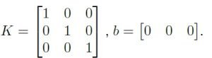
- MPE_SetAXLCalibrationParameters and MPE_SetGYRCalibrationParameters. They set scale factor matrix K and bias vector b to calibrate accelerometer and gyroscope readings. If 9DOF solution is chosen, also magnetometer data have to be calibrated with MPE_SetMAGCalibrationParameters parameters.
If those parameters are not available, they must be set as
It has to be noticed that, for a proper use of 9DOF orientation estimated, a calibrated magnetometer with a reference magnetic field norm of 400mG is mandatory.
MPE integration requires only 3 lines of code, which implement the following functionalities:
- MPE_Init. It must be invoked before running the logic. It allows to set all the configuration and initialization of filter parameters and internal variables.
- MPE_Update_6DOF or MPE_Update_9DOF. It runs the core functions of the logic, as depicted in the AlgorithmFlowchart, exploiting inertial data and sampled magnetic field if 9DOF mode is selected to compute orientation.
- MPE_GetOrientationQuaternion. It returns the current orientation in quaternion form. In addition MPE_GetEulerAnglesFromQuaternion can be used to convert orientation from quaternion to Euler angles representation.
2. Flowchart
The following block diagram describes the flow of operations that implement the MPE logic.

FIGURE 2.1 ALGORITHM FLOWCHART
3. References
The following lines contain general information about the library, such as version and date of publication, together with the contact details of the 221e internal staff responsible for maintaining and managing the library.
-
Authors and Referents
Giorgio Barzon
Roberto Bortoletto
Daniele Comotti -
Library Version
v2.1.2 -
Date
September 2026 -
Copyright
Copyright (c) 2020 All Rights Reserved by 221e srl. [email protected]
4. Requirements
The following lines contain information about the library size occupation, time execution and power concumption [3]. Tests and measurements have been done with a STM32WB55 MCU, clocked @16MHz, and including within a STM32CubeIDE firmware project the MPE static library compiled for ARM Cortex-M4. No optimization (i.e., -O0) has been applied during library compilation, while the firmware was -O2 optimized. The library has been compiled in a complete configuration (i.e., both 6DOF and 9DOF version available) and with 6DOF version only. Results are reported in the following tables.
| Configuration | FLASH Occupation [kB] | RAM Occupation [kB] |
|---|---|---|
| 6DOF only | 21.08 | 0.45 |
| Complete | 30.10 | 19.50 |
TABLE 4.1 MPE MEMORY OCCUPATION
| Timing [clock hits] | Timing @64MHz [ms] | Power Consumption @100Hz [uA] | |
|---|---|---|---|
| Average Value MPE_Update_6DOF | 8522 | 0.533 | 85 |
| Maximum Value MPE_Update_6DOF |
9620 | 0.601 | 96 |
| Average Value MPE_Update_9DOF | 10064 | 0.629 | 101 |
| Maximum Value MPE_Update_9DOF | 11559 | 0.722 | 116 |
TABLE 4.2 MPE EXECUTION TIMINGS
5. Example Documentation
5.1 MPE_Example.c
This is an example of library usage for MPE logic, based on accelerometer and gyroscope data, where:
- A proper initialization of MPE algorithm is shown
- Streaming of data is simulated by reading from a .txt file
- A correct call to MPE_Update_6DOF function is shown
#include<stdio.h> // Include C standard libraries
#include "MPEnMPE.h" // Include MPE.h
#define inputDataLength 9
float inputData[inputDataLength] = { 0, 0, 0, 0, 0, 0, 0, 0, 0}; // Gyr [dps], Axl [mg] and Mag [mG] triplets
int inputfrequency = 100; // Define data sampling frequency [Hz]
float gyro_noise_threshold = 0.0625; // Threshold used for gyroscope bias estimation [dps^2]
bool use_MPE_9DOF = false; // Flag for using MPE_6DOF or MPE_9DOF solution
// Calibration coefficients
float axl_coeff[] = { 1.0, 0, 0,
0, 1.0, 0,
0, 0, 1.0,
0, 0, 0 }; // Accelerometer scale factor matrix and bias [mg] parameters
float gyr_coeff[] = { 1.0, 0, 0,
0, 1.0, 0,
0, 0, 1.0,
0, 0, 0 }; // Gyroscope scale factor matrix and bias [dps] parameters
float mag_coeff[] = { 1.0, 0, 0,
0, 1.0, 0,
0, 0, 1.0,
0, 0, 0 }; // Magnetometer scale factor matrix and bias [mG] parameters
int main(void) {
// Open I/O files
FILE *fin = fopen("input_file.txt", "r"); // Open input file
FILE *fout = fopen("output_file.txt", "w"); // Open output file
// Set sampling time, from given frequency value
MPE_SetSamplingTime(inputfrequency); // Set MPE input frequency
// Set configuration / calibration coefficients
MPE_SetGyroscopeNoiseThreshold(gyro_noise_threshold); // Set gyroscope bias threshold
MPE_SetGYRCalibrationParameters(gyr_coeff); // Set gyroscope calibration matrix
MPE_SetAXLCalibrationParameters(axl_coeff); // Set accelerometer calibration matrix
if (MPE_9DOF)
MPE_SetMAGCalibrationParameters(mag_coeff); // Set magnetometer calibration matrix
MPE_Init(); // MPE_Init call
uint8_t i; // Support variable
// Main Loop
while (feof(fin) == 0) {
float inGyr[3];
float inAxl[3];
float inMag[3];
if (use_MPE_9DOF){
// Read data: Gyr.X Gyr.Y Gyr.Z Acc.X Acc.Y Acc.Z Mag.X Mag.Y Mag.Z
for (i = 0; i < (inputDataLength); i++) {
fscanf(fin, "%f", &inputData[i]);
}
// Get Mag data
inMag[0] = inputData[6];
inMag[1] = inputData[7];
inMag[2] = inputData[8];
}else{
// Read data: Gyr.X Gyr.Y Gyr.Z Acc.X Acc.Y Acc.Z
for (i = 0; i < inputDataLength-3; i++) {
fscanf(fin, "%f", &inputData[i]);
}
}
// Get IMU data
inGyr[0] = inputData[0];
inGyr[1] = inputData[1];
inGyr[2] = inputData[2];
inAxl[0] = inputData[3];
inAxl[1] = inputData[4];
inAxl[2] = inputData[5];
float q[4]; // Quaternion array
float ea[3]; // Euler angles array
if (use_MPE_9DOF){
MPE_Update_9DOF(inGyr, inAxl, inMag); // MPE_Update_9DOF call
}else{
MPE_Update_6DOF(inGyr, inAxl); // MPE_Update_6DOF call
}
MPE_GetOrientationQuaternion(q); // Get current quaternion
MPE_GetEulerAnglesFromQuaternion(q,ea); // Quaternion to Euler angles conversion [deg]
// Print current quaternion and Euler angles on file
fprintf(fout, "%fnt%fnt%fnt%fnt%fnt%fnt%fnn", q[0], q[1], q[2], q[3], ea[0], ea[1], ea[2]);
}
// Close I/O files
fclose(fin);
fclose(fout);
return 0;
}
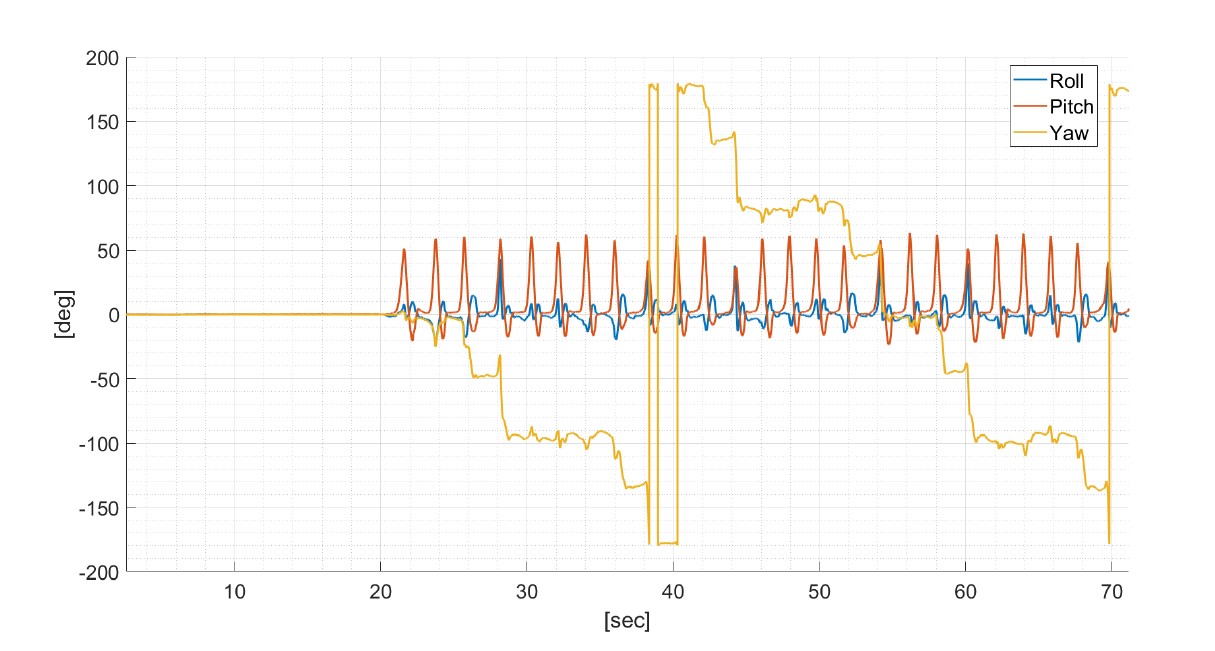
Figure 8.1 Output example
5.2 Visualization
A visual representation of the results is shown in the following ExampleFigure, where the results of a walk around a rectangular path are shown. The data were acquired with the 221e Muse device, installed on the user ankle.